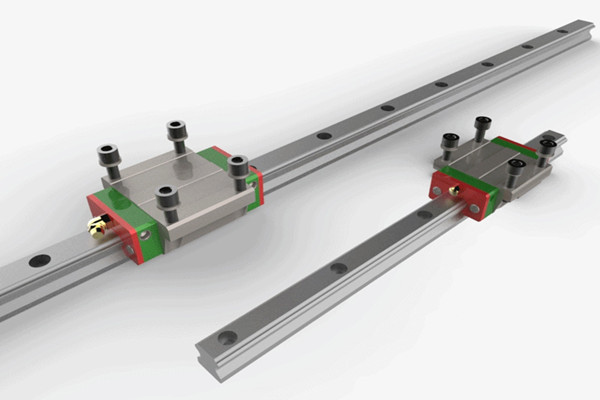
Linear guideway is designed for applications requiring precise movement with high bearing capacity. However, improper installation will increase unnecessary load, shorten service life and destroy the inherent stroke accuracy of linear guide rail system. Understanding and following the three installation specifications described below will help ensure that your installation achieves the required accuracy and will not fail prematurely.
1. Parallelism of guide rail
The most common installation method of linear guide rail is double track and four sliders. However, regardless of the number of sliders, when two tracks are used in parallel, if they are not installed within the parallelism tolerance specified by the manufacturer, additional side loads may occur. There are many methods for fixing guide rails and ensuring their straightness, from the most accurate method of machining reference edges for each guide rail, to the least accurate (and lowest cost) method of installing one guide rail using a straight edge or gauge, and using a connecting plate to “float” the second guide rail to an appropriate alignment position.
It is important to note that the allowable lateral force may be reduced if the guide rail is not installed on the reference edge or restraining strap. This is because the shear strength of guide rail mounting screws becomes the limiting factor of allowable lateral load without lateral holding force.
2. Vertical offset between guide rails
Guide rails used in parallel shall also meet the maximum allowable offset in the vertical direction. This is usually designated as S1, which is a function of the distance between guide rail and slider preload. The higher the car preload level, the smaller the allowable vertical offset. If this value is exceeded, rolling moment will be introduced into the frame, thus shortening the bearing life. When calculating the vertical offset, the height tolerance H of the slider must be considered. If the offset caused by height tolerance is larger than the allowable value, the guide rail with lower preload or higher precision should be used.
3. Vertical offset between sliders
When multiple sliders are used on the same track, the vertical offset between sliders (usually expressed as S2) becomes an important factor, and pitching moment can be exerted on the carriage. The allowable vertical offset is a function of the car length (standard, short or long) and the distance between the sliders. Similar to the offset between guide rails, the calculation of vertical offset between sliders should consider the height difference δ h between sliders. If the actual vertical offset is larger than the calculated allowable offset S2, a shorter version of the slider or a higher precision version must be used.
Of course, the correct installation involves other factors, many of which are not directly related to the components used, such as the base preparation, the geometry of the reference edge, and even the procedure of tightening the installation screws. Less demanding applications can usually achieve satisfactory results with less stringent installation procedures. But for the most critical and high-precision installation, strictly following the manufacturer’s installation and installation specifications will ensure the highest possible accuracy and avoid shortening the service life of the system.

 What are the different types of ball screws?
 Causes and solutions of damage to slide block of linear guide rail