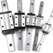
What fields can the linear module be used in?

ARESWIN Relying on years of accumulation and precipitation in the industry, linear modules have achieved energy savings in the mold industry, auto parts industry, home appliance industry, kitchenware industry, hardware plumbing equipment, glasses, jewelry, clocks, and medical equipment to achieve energy savings, save labor costs, and improve production efficiency.

1. The medical and pharmaceutical industries can also find traces of linear modules in the marking of medical devices and pharmaceutical packaging. For example, plastic mechanical cover marking, drug delivery inspection, sorting, and packaging have linear modules.

2. The electronic semiconductor industry With the great development of the digital age of innovation in the era of technology, electronic products have entered all aspects of our daily lives. Batteries, IT fields, precision welding, motor welding, sensors, refrigeration accessories welding, light guide plate marking, cables, LCD panel edges, integrated circuit (IC) marking, welding parts laser, soldering is everywhere but linear module applications.

3. Light industry, textile, printing and dyeing industry

The dyeing, spraying, crystal handicraft processing and other industries developed in the high-tech modern daily life textile industry and home furnishing field, applied to motion control can satisfy the people’s pursuit of a comfortable and elegant life, and can feel the new experience brought by excellent quality . The linear module embodies its own advantages.

4. Transportation and logistics industry

Linear modules are used in handling, palletizing, sorting, etc. in the traditional transportation and logistics industry… It can greatly save costs and complete all operations safely and efficiently.

5. Printing industry

The specific processing technology is realized through personalized customization.

6. Machinery, manufacturing and processing industries.

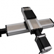
If you need to build a linear module XY,XYZ table, please contact us in time, and we will provide you with a complete set of solutions.

What are the advantages of linear modules in industry?

The linear module was originally invented and used by the Germans. Its wide application worldwide has brought tremendous changes to the automation industry.

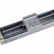
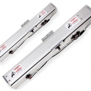
There are many types of linear modules. Compared with conventional transmission devices such as linear guides and ball screw linear actuators, they show greater advantages. The three advantages of linear modules are explained in detail below.

1. The speed of a single object can be increased by quickly reducing friction. Linear modules can increase the speed of linear motion by reducing the friction between interacting objects. At the same time, the positioning speed of the linear module is also very fast, and the time consumption is greatly reduced. The increase in positioning speed and linear motion speed means that the positioning speed and linear motion speed can be changed, and more work can be completed in a short time, that is, the work efficiency is significantly improved. The belt linear module is particularly prominent in terms of speed advantages.

2. High repetitive positioning accuracy and fast positioning speed does not mean that it affects the positioning accuracy of the linear module. While increasing the speed, it further improves the positioning accuracy of the linear module. Repeated positioning can be accurate at the same time, without the need for re-calibration and multiple operations. The parts can avoid errors. The linear slide has a variety of models and specifications to choose from, which is convenient to use, and there is no need to correct itself and the product in the short term. Ball screw linear slide It occupies a strong advantage in repeated accuracy levels, and it is very common in the contemporary laser manufacturing industry and laser cutting manufacturing industry.

3. Small size, long life, fast speed, and high precision are not all the advantages of linear modules, nor does it mean that linear modules are large in size. On the contrary, linear modules are smaller than existing transmission devices and are also used in precision equipment. Reason. For example, the service life of high-tech linear modules is basically more than 2000 (km).

At the same time, the latest reference price of machinery has been further reduced, and it has a long service life, which is suitable for automatic processing in large and small factories. The invention and use of linear modules provide the automation industry with faster speed and higher accuracy. At the same time, the longer life of linear modules further improves the cost-effectiveness of their use. In addition, the latest reference price of the linear module shows that the price of the linear module is more favorable, its advantages will be better highlighted, and its application range will be further expanded. Processing plants must develop and innovate before they can gain a firm foothold in the market competition of the manufacturing industry. The use of the best labor tool, the linear sliding table, is the first step for processing plants to keep up with the pace of the times.

What should we notice when mounting linear guide rail?

Linear guideway is designed for applications requiring precise movement with high bearing capacity. However, improper installation will increase unnecessary load, shorten service life and destroy the inherent stroke accuracy of linear guide rail system. Understanding and following the three installation specifications described below will help ensure that your installation achieves the required accuracy and will not fail prematurely.

1. Parallelism of guide rail

The most common installation method of linear guide rail is double track and four sliders. However, regardless of the number of sliders, when two tracks are used in parallel, if they are not installed within the parallelism tolerance specified by the manufacturer, additional side loads may occur. There are many methods for fixing guide rails and ensuring their straightness, from the most accurate method of machining reference edges for each guide rail, to the least accurate (and lowest cost) method of installing one guide rail using a straight edge or gauge, and using a connecting plate to “float” the second guide rail to an appropriate alignment position.

It is important to note that the allowable lateral force may be reduced if the guide rail is not installed on the reference edge or restraining strap. This is because the shear strength of guide rail mounting screws becomes the limiting factor of allowable lateral load without lateral holding force.

2. Vertical offset between guide rails

Guide rails used in parallel shall also meet the maximum allowable offset in the vertical direction. This is usually designated as S1, which is a function of the distance between guide rail and slider preload. The higher the car preload level, the smaller the allowable vertical offset. If this value is exceeded, rolling moment will be introduced into the frame, thus shortening the bearing life. When calculating the vertical offset, the height tolerance H of the slider must be considered. If the offset caused by height tolerance is larger than the allowable value, the guide rail with lower preload or higher precision should be used.

3. Vertical offset between sliders

When multiple sliders are used on the same track, the vertical offset between sliders (usually expressed as S2) becomes an important factor, and pitching moment can be exerted on the carriage. The allowable vertical offset is a function of the car length (standard, short or long) and the distance between the sliders. Similar to the offset between guide rails, the calculation of vertical offset between sliders should consider the height difference δ h between sliders. If the actual vertical offset is larger than the calculated allowable offset S2, a shorter version of the slider or a higher precision version must be used.

Of course, the correct installation involves other factors, many of which are not directly related to the components used, such as the base preparation, the geometry of the reference edge, and even the procedure of tightening the installation screws. Less demanding applications can usually achieve satisfactory results with less stringent installation procedures. But for the most critical and high-precision installation, strictly following the manufacturer’s installation and installation specifications will ensure the highest possible accuracy and avoid shortening the service life of the system.